- 您现在的位置:买卖IC网 > Sheet目录471 > MAX2021ETX+T (Maxim Integrated)IC MOD/DEMOD 36-TQFN
MAX2021
High-Dynamic-Range, Direct Up-/Downconversion
650MHz to 1200MHz Quadrature Mod/Demod
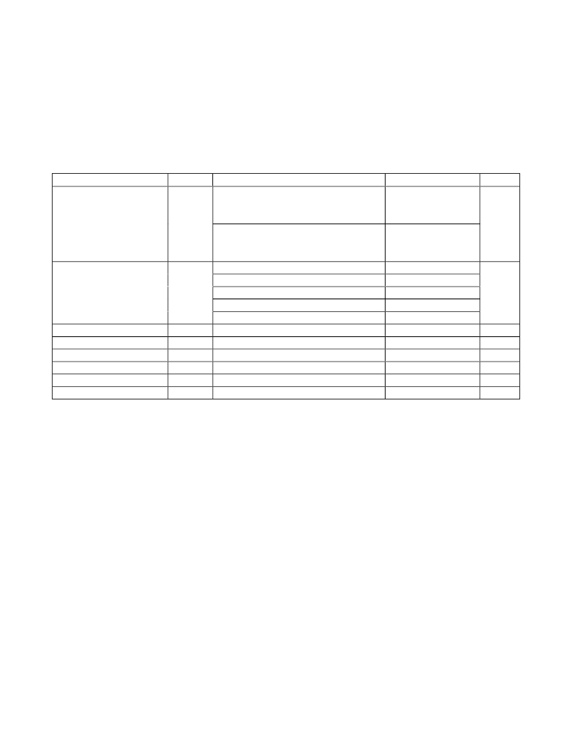
AC ELECTRICAL CHARACTERISTICS (Demodulator LO = 965MHz) (continued)
(Typical Application Circuit when operated as a demodulator. I/Q outputs are recombined using network shown in Figure 5. Losses of
combining network not included in measurements. RF and LO ports are driven from 50 Ω sources. Typical values are for T A = +25°C,
V CC = 5.0V, I/Q DC voltage return = 0V, P RF = 0dBm, P LO = 0dBm, f RF = 780MHz, f LO = 965MHz, f IF = 185MHz, unless otherwise noted.)
PARAMETER
SYMBOL
CONDITIONS
MIN
TYP
MAX
UNITS
f RF1 = 780MHz, f RF2 = 781MHz,
P RF1 = P RF2 = 0dBm, f IF1 = 185MHz,
70.1
Input Second-Order Intercept
Point
IIP2
f IF2 = 184MHz, f IF1 + f IF2 term
f RF1 = 780MHz, f RF2 = 735MHz,
P RF1 = P RF2 = 0dBm, f IF1 = 185MHz,
70.2
dBm
f IF2 = 230MHz, f IF1 + f IF2 term
2LO - 2RF, f RF = 872.5MHz, P RF = -10dBm
84
Spurious Relative to a
Fundamental at 780MHz
Input Compression from Linear
I/Q Gain Mismatch
I/Q Phase Mismatch
1dB Conversion Loss Flatness
RF Return Loss
LO Return Loss
3LO - 3RF, f RF = 903.333MHz, P RF = -10dBm
3RF - 2LO, f RF = 705MHz, P RF = -10dBm
4RF - 3LO, f RF = 770MHz, P RF = -10dBm
5RF - 4LO, f RF = 809MHz, P RF = -10dBm
P RF = 0dBm to 21dBm
f LO = 965MHz, f LO > f RF
99
105
114
115
0.17
0.05
0.4
400
17
12
dBc
dB
dB
Degrees
MHz
dB
dB
Note 5:
Note 6:
Note 7:
Note 8:
Note 9:
Recommended functional range. Not production tested. Operation outside this range is possible, but with degraded
performance of some parameters.
Guaranteed by design and characterization.
Parameter also applies to demodulator topology.
Single-carrier WCDMA with 10.5dB peak-to-average ratio at 0.1% complementary cumulative distribution function,
P RF = -10dBm (P RF is chosen to give -65dBc ACLR).
No baseband drive input. Measured with the inputs terminated in 50 Ω . At low output levels, the output noise is thermal.
Note 10: The output noise versus P OUT curve has the slope of LO noise (Ln dBc/Hz) due to reciprocal mixing.
Note 11: Conversion loss is measured from the single-ended RF input to single-ended combined baseband output.
Note 12: The LO noise (L = 10 (Ln/10) ), determined from the modulator measurements can be used to deduce the noise figure
under-blocking at operating temperature (Tp in Kelvin), F BLOCK = 1 + (Lcn - 1) Tp / To + LP BLOCK / (1000kTo), where
To = 290K, P BLOCK in mW, k is Boltzmann’s constant = 1.381 x 10 (-23) J/K, and Lcn = 10 (Lc/10) , Lc is the conversion loss.
Noise figure under-blocking in dB is NF BLOCK = 10 x log (F BLOCK ). Refer to Application Note 3632: Wideband LO Noise in
Passive Transmit-Receive Mixer ICs.
Maxim Integrated
5
发布紧急采购,3分钟左右您将得到回复。
相关PDF资料
MAX2022ETX+T
IC MOD 1500MHZ TO 2500MHZ 36TQFN
MAX2022EVKIT
EVAL KIT FOR MAX2022
MAX2023ETX+T
IC MOD/DEMOD HI DYN RNG 36-TQFN
MAX2027EUP+D
IC AMP VAR GAIN 20-TSSOP
MAX2027EVKIT
EVAL KIT FOR MAX2027
MAX2029ETP+T
IC MIXER UP/DOWN HI LIN 20-TQFN
MAX2031EVKIT
EVAL KIT FOR MAX2031
MAX2032ETP+
IC MIXER UP/DOWN CONVER 20TQFN
相关代理商/技术参数
MAX2021ETX-T
功能描述:调节器/解调器 0.75GHz-1.2GHz Quad Mod/Demod RoHS:否 制造商:Texas Instruments 封装 / 箱体:PVQFN-N24 封装:Reel
MAX2021EVKIT
功能描述:射频开发工具 RoHS:否 制造商:Taiyo Yuden 产品:Wireless Modules 类型:Wireless Audio 工具用于评估:WYSAAVDX7 频率: 工作电源电压:3.4 V to 5.5 V
MAX2022
制造商:MAXIM 制造商全称:Maxim Integrated Products 功能描述:High-Dynamic-Range, Direct Upconversion 1500MHz to 2500MHz Quadrature Modulator
MAX20-22.0C
制造商:MDE 制造商全称:MDE Semiconductor, Inc. 功能描述:HIGH CURRENT TRANSIENT VOLTAGE SUPPRESSOR (TVS) DIODE
MAX20-22.0CA
制造商:MDE 制造商全称:MDE Semiconductor, Inc. 功能描述:HIGH CURRENT TRANSIENT VOLTAGE SUPPRESSOR (TVS) DIODE
MAX2022_1
制造商:MAXIM 制造商全称:Maxim Integrated Products 功能描述:Evaluation Kit
MAX2022_12
制造商:MAXIM 制造商全称:Maxim Integrated Products 功能描述:High-Dynamic-Range, Direct Up/ Downconversion 1500MHz to 3000MHz Quadrature Modulator/Demodulator
MAX2022ETX
功能描述:调节器/解调器 1.5GHz-2.5GHz Quad Mod/Demod RoHS:否 制造商:Texas Instruments 封装 / 箱体:PVQFN-N24 封装:Reel
