- 您现在的位置:买卖IC网 > Sheet目录471 > MAX2021ETX+T (Maxim Integrated)IC MOD/DEMOD 36-TQFN
�� �
�
�MAX2021�
�High-Dynamic-Range,� Direct� Up-/Downconversion�
�650MHz� to� 1200MHz� Quadrature� Mod/Demod�
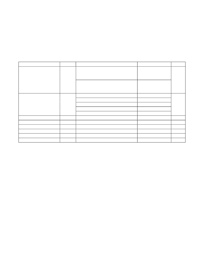
�AC� ELECTRICAL� CHARACTERISTICS� (Demodulator� LO� =� 965MHz)� (continued)�
�(Typical� Application� Circuit� when� operated� as� a� demodulator.� I/Q� outputs� are� recombined� using� network� shown� in� Figure� 5.� Losses� of�
�combining� network� not� included� in� measurements.� RF� and� LO� ports� are� driven� from� 50� Ω� sources.� Typical� values� are� for� T� A� =� +25°C,�
�V� CC� =� 5.0V,� I/Q� DC� voltage� return� =� 0V,� P� RF� =� 0dBm,� P� LO� =� 0dBm,� f� RF� =� 780MHz,� f� LO� =� 965MHz,� f� IF� =� 185MHz,� unless� otherwise� noted.)�
�PARAMETER�
�SYMBOL�
�CONDITIONS�
�MIN�
�TYP�
�MAX�
�UNITS�
�f� RF1� =� 780MHz,� f� RF2� =� 781MHz,�
�P� RF1� =� P� RF2� =� 0dBm,� f� IF1� =� 185MHz,�
�70.1�
�Input� Second-Order� Intercept�
�Point�
�IIP2�
�f� IF2� =� 184MHz,� f� IF1� +� f� IF2� term�
�f� RF1� =� 780MHz,� f� RF2� =� 735MHz,�
�P� RF1� =� P� RF2� =� 0dBm,� f� IF1� =� 185MHz,�
�70.2�
�dBm�
�f� IF2� =� 230MHz,� f� IF1� +� f� IF2� term�
�2LO� -� 2RF,� f� RF� =� 872.5MHz,� P� RF� =� -10dBm�
�84�
�Spurious� Relative� to� a�
�Fundamental� at� 780MHz�
�Input� Compression� from� Linear�
�I/Q� Gain� Mismatch�
�I/Q� Phase� Mismatch�
�1dB� Conversion� Loss� Flatness�
�RF� Return� Loss�
�LO� Return� Loss�
�3LO� -� 3RF,� f� RF� =� 903.333MHz,� P� RF� =� -10dBm�
�3RF� -� 2LO,� f� RF� =� 705MHz,� P� RF� =� -10dBm�
�4RF� -� 3LO,� f� RF� =� 770MHz,� P� RF� =� -10dBm�
�5RF� -� 4LO,� f� RF� =� 809MHz,� P� RF� =� -10dBm�
�P� RF� =� 0dBm� to� 21dBm�
�f� LO� =� 965MHz,� f� LO� >� f� RF�
�99�
�105�
�114�
�115�
�0.17�
�0.05�
�0.4�
�400�
�17�
�12�
�dBc�
�dB�
�dB�
�Degrees�
�MHz�
�dB�
�dB�
�Note� 5:�
�Note� 6:�
�Note� 7:�
�Note� 8:�
�Note� 9:�
�Recommended� functional� range.� Not� production� tested.� Operation� outside� this� range� is� possible,� but� with� degraded�
�performance� of� some� parameters.�
�Guaranteed� by� design� and� characterization.�
�Parameter� also� applies� to� demodulator� topology.�
�Single-carrier� WCDMA� with� 10.5dB� peak-to-average� ratio� at� 0.1%� complementary� cumulative� distribution� function,�
�P� RF� =� -10dBm� (P� RF� is� chosen� to� give� -65dBc� ACLR).�
�No� baseband� drive� input.� Measured� with� the� inputs� terminated� in� 50� Ω� .� At� low� output� levels,� the� output� noise� is� thermal.�
�Note� 10:� The� output� noise� versus� P� OUT� curve� has� the� slope� of� LO� noise� (Ln� dBc/Hz)� due� to� reciprocal� mixing.�
�Note� 11:� Conversion� loss� is� measured� from� the� single-ended� RF� input� to� single-ended� combined� baseband� output.�
�Note� 12:� The� LO� noise� (L� =� 10� (Ln/10)� ),� determined� from� the� modulator� measurements� can� be� used� to� deduce� the� noise� figure�
�under-blocking� at� operating� temperature� (Tp� in� Kelvin),� F� BLOCK� =� 1� +� (Lcn� -� 1)� Tp� /� To� +� LP� BLOCK� /� (1000kTo),� where�
�To� =� 290K,� P� BLOCK� in� mW,� k� is� Boltzmann’s� constant� =� 1.381� x� 10� (-23)� J/K,� and� Lcn� =� 10� (Lc/10)� ,� Lc� is� the� conversion� loss.�
�Noise� figure� under-blocking� in� dB� is� NF� BLOCK� =� 10� x� log� (F� BLOCK� ).� Refer� to� Application� Note� 3632:� Wideband� LO� Noise� in�
�Passive� Transmit-Receive� Mixer� ICs.�
�Maxim� Integrated�
�5�
�发布紧急采购,3分钟左右您将得到回复。
相关PDF资料
MAX2022ETX+T
IC MOD 1500MHZ TO 2500MHZ 36TQFN
MAX2022EVKIT
EVAL KIT FOR MAX2022
MAX2023ETX+T
IC MOD/DEMOD HI DYN RNG 36-TQFN
MAX2027EUP+D
IC AMP VAR GAIN 20-TSSOP
MAX2027EVKIT
EVAL KIT FOR MAX2027
MAX2029ETP+T
IC MIXER UP/DOWN HI LIN 20-TQFN
MAX2031EVKIT
EVAL KIT FOR MAX2031
MAX2032ETP+
IC MIXER UP/DOWN CONVER 20TQFN
相关代理商/技术参数
MAX2021ETX-T
功能描述:调节器/解调器 0.75GHz-1.2GHz Quad Mod/Demod RoHS:否 制造商:Texas Instruments 封装 / 箱体:PVQFN-N24 封装:Reel
MAX2021EVKIT
功能描述:射频开发工具 RoHS:否 制造商:Taiyo Yuden 产品:Wireless Modules 类型:Wireless Audio 工具用于评估:WYSAAVDX7 频率: 工作电源电压:3.4 V to 5.5 V
MAX2022
制造商:MAXIM 制造商全称:Maxim Integrated Products 功能描述:High-Dynamic-Range, Direct Upconversion 1500MHz to 2500MHz Quadrature Modulator
MAX20-22.0C
制造商:MDE 制造商全称:MDE Semiconductor, Inc. 功能描述:HIGH CURRENT TRANSIENT VOLTAGE SUPPRESSOR (TVS) DIODE
MAX20-22.0CA
制造商:MDE 制造商全称:MDE Semiconductor, Inc. 功能描述:HIGH CURRENT TRANSIENT VOLTAGE SUPPRESSOR (TVS) DIODE
MAX2022_1
制造商:MAXIM 制造商全称:Maxim Integrated Products 功能描述:Evaluation Kit
MAX2022_12
制造商:MAXIM 制造商全称:Maxim Integrated Products 功能描述:High-Dynamic-Range, Direct Up/ Downconversion 1500MHz to 3000MHz Quadrature Modulator/Demodulator
MAX2022ETX
功能描述:调节器/解调器 1.5GHz-2.5GHz Quad Mod/Demod RoHS:否 制造商:Texas Instruments 封装 / 箱体:PVQFN-N24 封装:Reel